Discover. Connect. Act.
Philadelphia Water Department
Water and Drainage History Course
Module 5
Second Philadelphia Water Works: Steam Power and Water
Power at Fairmount, 1815-1909
Unless otherwise noted, all images are from
the PWD Historical Collection.
Main sources for this section include Nelson Blake, Water for the Cities
(Syracuse University Press, 1956)
and Jane Mork Gibson, “Fairmount Water Works”
(Bulletin, Philadephia Museum of Art, Vol. 84, No. 360, 361, Summer
1988).

The 1815 Engine House (shown here in an 1819 print) housed
two steam-powered pumps that drew water from the Schuylkill River and pumped
it into the reservoirs above the building, on top of Faire Mount. The artist
showed smoke pouring from the south chimney, indicating that the South Engine
was operating. The bridge just downstream was the covered Upper Ferry Bridge,
an incredible 340 feet long, also completed in 1815. Designed and constructed
by Lewis Wernwag, a native of Germany who had studied engineering there,
the bridge opened in 1813. Formally called the Upper Ferry Bridge, it was
also known as the “Colossus of Philadelphia” because — like
the mythical Colossus of Rhodes — the bridge was held up only by piers
at its two ends, with no intermediate supports. Made entirely of wood, the
bridge was destroyed by fire in 1838.
By 1811, it was clear to the Watering Committee, to City Councils, and to citizens who used the water supplied by the Centre Square Works that this original system would be unable to meet the city’s future water needs. In October of that year, the Watering Committee charged Frederick Graff, the current chief engineer, and John Davis, who had served as the water system’s first chief engineer, with the task of investigating other options by which the city might acquire a more reliable and abundant supply of water. In December, Graff and Davis finished their report, which gave the Committee five alternatives. Among these were a couple of old ideas that were quickly removed from consideration. Tapping the Wissahickon with an aqueduct was dismissed because of the expense, and finishing the Delaware and Schuylkill Canal and using it as a water source was found, on closer inspection, to be impractical. They also proposed moving the Centre Square engine to the Schuylkill Water Works, so one engine could be a back-up to the other. A fourth alternative was to overhaul the existing system.
It was a fifth suggestion that both engineers favored, and which was ultimately adopted: building a new water works about a mile upstream from the Chestnut Street intake of the Schuylkill Water Works, at the foot of Faire Mount (also known as Morris’s Hill). A pumping station there with two steam engines would be more reliable, with one engine serving as a back-up to the other. At the top of the hill they proposed building a large reservoir that would hold three million gallons, a great improvement over the wooden tanks at Centre Square, which held less than 18,000 gallons. From the heights of the reservoir, fifty-six feet above the highest ground in the city, water would flow by gravity into the existing system of pipes to businesses, homes and hydrants. This new system at Fairmount followed, but greatly expanded, the model established by Latrobe in the original water works: pumping to elevated storage and distribution by gravity flow.
Not everyone favored the change. Some prescient citizens suggested using the water power of the Schuylkill to pump water into the reservoirs rather than relying on steam engines—which is exactly what the city resorted to eight years later. But in the meantime, Graff and Davis received ample support for their steam-powered works. The plan was approved, the site at Faire Mount was purchased and ground was broken for the engine house at the foot of the hill on August 1, 1812. The new works began operation three years later, on September 7, 1815.

Graff and Davis decided that Schuylkill River water withdrawn
at Fairmount should be transmitted from the reservoir to the existing network
of wooden pipes created for the city’s original water works. The iron
transmission mains constructed for that purpose, drawn as gold lines in
the plan above, generally followed the grid of existing and planned streets
from Fairmount Reservoir (upper left corner) to Centre Square (lower right
corner). The lone diagonal section was built alongside the Philadelphia
and Columbia Railroad (later purchased by the Pennsylvania Railroad), now
the location of Pennsylvania Avenue. To
see the full map, click here.
The new water works did prove more reliable, and did serve to greatly increase the supply, but it was still plagued by several problems. One was the system of wooden distribution pipes. In addition to leaks at many joints (where logs were joined and secured with an iron band), Graff admitted that friction in these pipes had been underestimated, and the many right angles taken by the pipes at street corners also slowed the flow of water. This meant that the water pressure diminished more than anticipated as water traveled farther from the reservoir, which was a problem for some users at the far end of these pipelines. As a solution to this problem, the Watering Committee resolved in 1818 to lay only iron pipes for new and replacement mains. Over the next three decades new cast iron pipes were laid and old wooden ones replaced until, by 1858, the last wooden pipes were taken out of service. The cast iron pipes had less friction, leaked less readily, and lasted far longer than the wooden pipes, in many cases a hundred years or more. A few iron pipes laid in the 1820s are still in service in the oldest parts of the city.

Frederick Graff’s drawing of the 1815 steam engine,
adapted from a design by Englishmen Matthew Boulton and James Watt, shows
the engine from the north, with Faire Mount and the reservoirs to the left
of the drawing and the river to the right. The 1815 engine sat on the south
side of the Engine House and was thus called the South Engine. As Graff
indicated in his drawing, the Engine House was essentially open from river
level to the roof in order to accommodate the massive beam and fly wheel
of the two engines. While Graff showed the crank attached to the axle of
the fly wheel, he left the crank shaft and the pump out of the drawing.
The North Engine, designed and built in 1816 by Philadelphian Oliver Evans,
advanced steam engines’ operating pressures from 2 pounds per square
inch (psi) to 200 psi, a significant technological achievement.
Another problem with the system was the steam engines themselves. Steam power was costly, with the wood burned to fire the steam boilers being the main expense. Only one engine was run at a time, and when it was suggested that both engines be run simultaneously to increase the supply, doubling the use of fuel was deemed prohibitive. Steam engines were still relatively new technology at the time, their construction and materials had yet to be standardized, and the boilers sometimes exploded. Two such explosions at Fairmount, in 1818 and 1821, killed several people, and provided further impetus to find a cheaper, more reliable, and safer power source for the pumps.
The solution was to adopt a suggestion made earlier by prescient citizens: harnessing the power of the Schuylkill River itself to pump river water into the reservoir. To accomplish this goal, the Watering Committee entered into an agreement with the newly-chartered Schuylkill Navigation Company, to which the state legislature had granted control of the water rights on the river. The City also paid damages to several factory owners at the Falls of Schuylkill, six miles upstream, whose water power would be flooded and thus destroyed by th erection of the dam at Fairmount and the subsequent raising of the water level of the river above the dam.
The Navigation Company proposed to build a system of canals, locks, dams and slackwater pools to make the Schuylkill navigable from tidewater to the coal fields in Schuylkill County, 115 miles upstream. In return for the right to use the river’s water for power and as a supply for its citizens, the city agreed to build a dam at Fairmount along with a canal and locks to allow boats to get around the dam. The river was about 1,000 feet wide at the point of the dam, which would be the longest in the United States at that time. Construction began in 1819, the work on the dam undertaken by Captain Ariel Cooley, of Chicopee, Massachusetts.
The river was impounded by four distinct structures. An earth-filled masonry wall doubled as the wall of the lock at the entry to the canal on the western side of the river. A spillway, about 1,200 feet long, consisted of a series of wooden cribs built diagonally across the river the lessen the effects of freshets (or floods). A mound of earth (called the mound dam) 270 feet long was built where the mud on the river bottom was too deep to anchor wooden cribs. The fourth structure was the hollow masonry structure of the millhouse itself, 238 feet long, which housed the water wheels. Behind this building as the mill race (or forebay), 419 feet long and about 90 feet wide. The purpose of the forebay was to bring the river water, impounded behind this four-part dam, into the mill house through gates in the forebay wall, into flumes leading to the water wheels.
Each massive wheel, fifteen feet wide and fifteen or sixteen feet in diameter, turned at eleven to fourteen revolutions per minute, powered by the weight of water as it filled the long buckets affixed to the circumference of the wheel. A crank on the axle of the wheel tramsmitted the power generated by the turning wheel to the shaft of a pump. The pump sucked water out of the flume and pushed it through a pipe to the reservoir atop Fairmount.

“Ground Plan and Elevation of the Fairmount Dam and
Water Works, engraved by Robert Tiller, 1822. (Free Library of Philadelphia)
The illustrative part of this engraving is based on a painting by Thomas
Birch; the plan is based on a drawing by Frederick Graff. Shown (l to r)
are the Canal and Locks, Spillway, Mound Dam, 1822 Mill House, Forebay,
1815 Engine House, and Reservoirs. The rocks depicted in the river’s
channel, downstream of the west side of the Spillway, are still visible
at every low tide.

Based on its more modern appearance, signature,
lettering, and date, we can assume that this 1843 drawing of Faire Mount
and its Water Works, drawn in an academic style, was made by Frederic Graff,
Jr., then 26 years old, rather than by his father. Besides showing the three
basins added to the Reservoir since 1822, Graff, Jr.included the North and
South Gardens and the Wire Bridge, an early and influential wire-cable suspension
bridge, on the former site of the Colossus of Philadelphia, designed by
Charles Ellet, Jr. Graff also showed the tracks of the Philadelphia and
Columbia Railroad, later purchased by the Pennsylvania Railroad, slicing
off the corner of the North Garden. These tracks once ran down the middle
of Pennsylvania Avenue; since the late 1890s, they have run underneath it.
(Franklin Institute)

This plan of Fairmount and vicinity, drawn in 1839 by Frederick Graff, Sr.,
shows a birds-eye view of the same details as the isometric view (above)
created by his son four years later. The largest, eastern basin of the reservoir
had not yet been divided into two.The South Garden was just one year from
completion; because of the lack of detail, the plan for the North Garden
appears to have been little more than a proposal. The bed of the Philadelphia
and Columbia Railroad is shown bracketed by Pennsylvania Avenue. (Franklin
Institute)
The first water flowed over the dam on July 23, 1821. By July of 1822, the first water wheel was installed and at work in the mill house. By the end of October two more wheels were installed, and the steam engines were taken out of service. As the city grew and the need for water grew with it, more wheels were installed and more reservoirs built on the hill. By 1837 the full complement of four reservoirs atop Fairmount were completed, with an aggregate capacity of xxx million gallons. By 1843 the mill house had reached its capacity, with eight water wheels in operation. By then the engine house had been converted into a saloon serving refreshments, and the quarry to the south of the water works had been transformed into the South Garden and Esplanade. With a staircase leading up to the heights of the reservoir providing beautiful views of the river to the west and the city to the east, the Fairmount Water Works became one of the city’s must-see tourist destinations.

View of Fairmount Water Works with the Schuylkill River in
the Distance. (Free Library of Philadelphia) This 1838 view, by John T.
Bowen, “captures the pleasures of Fairmount in its heyday,” writes
historian Jane Mork Gibson. “The neat beauty of the works set into
a gentle landscape, steep paths and steps that offered an exhilirating contrast
to the general flatness of Philadelphia, as well as the excitement of boat
races on the river and refreshments offered in the former Engine House,
all prompted the admiring comments of visitors.”
Seeing the water wheels running at full power was a highlight of a visit to the water works. The interior of the mill house was designed so that the public could observe the machinery in operation, with two entrances leading to a balcony from which to view the massive wheels. Visitors found an endless fascination in the practically noiseless flowing of the water, the turning of the wheels, and the movement of the pumps. Outside, the roof of the mill house served as a popular promenade beside the Forebay.

“Fairmount Waterworks. From the forebay.” (From
nature & on stone G. Lehman; Published by C.G. Childs & G. Lehman,
1833. Free Library of Philadelphia, Print & Picture Collection) Visitors
to the Fairmount Water Works were invited to stroll on the roof of the 1822
(Old) Mill House and, as one figure was captured in this print, to enter
it through the South Entrance Portal, topped by William Rush’s sculpture,
“Allegory of the Water Works.” Climbing the wooden staircases
to the gazebo on the cliff face and to the top of the reservoir embankment
was part of the excursion. The gentle jet of water rising from William Rush’s
“Allegory of the Schuylkill River (Nymph and Bittern)” was depicted
just to the left of, and above, the swans. The wooden sculpture was later
cast in bronze and moved to the fountain in the South Garden.

Fairmount Water Works, by W. H. Bartlett, 839. (Free Library
of Philadelphia, Print & Picture Collection). This engraving from an
1839 painting by William Bartlett shows the porch added to the Engine House
about 1835 and the two gazebos built at the same time, all added to welcome
visitors to the Water Works and a new saloon, or restaurant, in the Engine
House. The powerful jet of water rising from the fountain in the South Garden,
fed by a dedicated pipe under the full pressure of the reservoir, was depicted
against the green foliage on the west slope of Faire Mount, near the east
end of the Colossus. A barge is making its way downstream through the canal,
headed under the Colossus to the busy port city of Philadelphia.

Fairmount. Daguerreotyped by W. S. Porter, Philadelphia,
May 22d, 1848. Panoramic photographs were popular among photographers and
the public alike. They made it easier for the viewer to imagine that she
or he was at the Water Works. To see larger version, click
here.
Describing a visit to Fairmount in 1840, Thomas Ewbank, inventor and manufacturer,
wrote:
“It is impossible to examine these works without paying homage to the science and skill displayed in their design and execution; in these respects no hydraulic works in the Union can compete, nor do we believe they are excelled by any in the world. Not the smallest leak in any of the joints was discovered; and, with the exception of the water rushing on the wheels, the whole operation of forcing up daily millions of gallons into the reservoirs on the mount, and thus furnishing in abundance one of the first necessaries of life to an immense population, was performed with less noise than is ordinarily made in working a smith’s bellows! The picturesque location, the neatness that reigns in the buildings, the walks around the reservoirs and the grounds at large, with the beauty of the surrounding scenery, render the name of this place singularly appropriate.”[1]

Fairmount Gardens, with the Schuylkill Bridge (Philadelphia).
This 1839 engraving, published in London, shows a view of the South Garden
from the walkways that brought visitors up the cliffside to the overlooks
at the height of the reservoirs. The fountain used the pressure of the reservoirs
and was a a delightful refreshment in hot weather, and a wonder at all times.
One anachonistic element of this engraving is the Upper Ferry Bridge, which
burned the year before the print was published. Harding’s Hotel, a
popular resort, is at the western end of the bridge.
European visitors were greatly impressed with the beauty and the power of the works, especially since it had been conceived and built in this country by locally trained engineers. Charles Dickens visited and had kind words for Fairmount, and English novelist Frances Trollope offered high praise as she recorded her visit to the waterworks in 1830. She considered it as deserving of fame as the water-works at Versailles, and called it “one of the very prettiest spots the eye can look upon.”[2] In 1851, in an attempt to provide more water more efficiently, a new technology was given a try at Fairmount. Frederick Graff Jr., who had succeeded his father as chief engineer, installed an experimental Jonval turbine, a type of horizontal waterwheel introduced in this country by the French engineer Emile Geyelin. (Portions of this turbine can still be viewed at the Water Works Interpretive Center.) This turbine proved so successful that a new mill house was constructed on the mound dam in between 1859 and 1862, and old mill house was altered between 1868 and 1872. With this conversion, the pumping formerly provided by the eight waterwheels was now undertaken by seven Jonval turbines.

The Farimount Water Works after about 1885, showing (l to r) the Mound Dam,
the New Mill House, and the Old Mill House. The original Engine House, by
this time in use as a Saloon serving refreshments, is mostly hidden behind
the trees on the left. In the river below the dam and in front of the water
works are (l) a covered barge for swimming, and (r) a boat rental concession,
both of which satisfied some of the recreational needs of Philadelphians.
The four open gates of the Mill Houses’ exit flumes, discharging water
that had turned the turbines within the building, indicated that at least
four of the seven turbines were in operation that day.

Jonval Turbines at in the New Mill House (built 1862) at
Fairmount. From a stereoview ca. 1870. Engineer
Emile Geyelin brought the technology for the turbines from France in 1849
and built a successful business from scratch, selling turbines and designing
installations for them up and down the east coast of the United States.
The large clock in the Mill House helped the operator accurately record
running times for the turbines. The roof of the Mill House, designed to
be fire-proof and space-saving, incorporated narrow brick vaults between
the flanges of wrought-iron beams that sat on massive, composite, riveted,
wrought-iron joists, all supported by cylindrical cast-iron columns. This
innovative structural system, manufactured without wooden components at
the Phoenix Iron Works in nearby Phoenixville, PA., revolutionized the architecture
of industrial, utility, and transportation structures, including subsequent
renovations to the Old Mill House and to the roof of the 1851 Turbine and
Pump Room. The air vessels in the photograph — critical shock-absorbing
components of the pumping system that dampened potentially-destructive water
hammer – and the columns supporting the roof were decorated with multiple
colors of paint in the Victorian style, creating an attractive interior.
By then Fairmount had become the prototype of a water-supply system for growing urban areas in the United States and abroad. Graff acted as consultant for more than thirty-seven other waterworks, and Philadelphia became the “Mecca of the hydraulic engineer,” according to Emile Geyelin. [3] In 1844 the Fairmount Water Works supplied an average of 5.3 million gallons of water per day to 28,082 water users. Expenditures were $29,713, and the amount paid into the treasury was $151,501. This marked a high point for revenues, generated, in part, by water rates paid by neighboring districts where assessments were fifty percent above the rates paid by Philadelphians.
The conversion to turbines marked the last of the innovations at Fairmount. Beginning in the 1840s the city began purchasing land upstream of Fairmount, in an attempt to protect the Schuylkill River from pollution. The largest purchases of thousands of upstream acres in the late 1860s and early 1870s, giving form to Fairmount Park as we know it today.

“Plan of Lemon Hill and Sedgley Park, Fairmount and Adjoining Property.”
Drawn by Frederick Graff. Jr., 1851.(Franklin Institute) Early purchases
of the Sedgley and Lemon Hill estates were the beginnings of Fairmount Park.
This land was purchased as public parkland, with the added motivation of
protecting the river bank immediately upstream from development with potentially
polluting industries. The small Water Works just upstream of Sedgley Park
– the Spring Garden Water Works, built in 11845 by Northern Liberties
and Spring Garden Districts, when its citizens refused to continue paying
the City’s for water supplied from the the Fairmount Water Works. After
the Spring Garden Water Works became part of the City’s water system
(upon Consolidation in 1854), it was expanded and played a vital role until
1909.
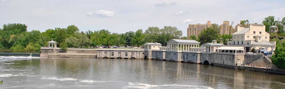
In spite of this attempt at watershed protection, as the century wore on the river grew more polluted. Epidemics of typhoid fever and other water-borne diseases were annual events, with typhoid alone killing more than 27,000 citizens in the half-century following the end of the Civil War. Eventually filtration of the city’s water supply to remove disease-causing bacteria was implemented as a solution. But Fairmount, with the limited land on the hill, had no room for the large filters required to purify the polluted river water. Five filtration plants were built elsewhere in the city, and once they were in operation, in 1909, the Fairmount Water Works was decommissioned as part of the city’s public water supply. For a couple of years one manufacturer continued to use raw water pumped at Fairmount for industrial processes, but in 1911 the water works at Fairmount was shut down completely.

Repairs being made to the Fairmount Dam in 1904. Part of Boathouse Row is
in the background.
FOOTNOTES
[1] Thomas Ewbank, A Descriptive and Historical Account of Hydraulic and Other Machines for Raising Water. (New York, 1842), p. 301
[2] Frances Trollope, Domestic Manners of the American. Vol. 2. London: Whitaker, Treacher & Co., 1832, p. 74-75.
[3] Emile Geyelin, “Growth of the Philadelphia Water Works” (Proceedings of the American Water Works Association, Philadelphia, 1891, p. 21).
RETURN to HISTORY COURSE HOME PAGE
All contents © 2015 Philadelphia Water Department